IanB
-
Posts
437 -
Joined
-
Last visited
Content Type
Profiles
Forums
Downloads
Everything posted by IanB
-
Casiotone CT 6500 - Turns On , No Sound
IanB replied to HAILHAIL's topic in Classic Casio Discussion
@Aaron Wright Okay, so let's check I understand you correctly. We have a period of 2 seconds (so to be pedantic it's .5Hz ) which I'll call Up and Down for want of something better. When you press a key, the CT's CPU assigns it to one of the two 933s- if it is during the Up period, it is assigned to 933 A, if it's pressed during the Down period, it's assigned to 933 B. So it actually starts sounding immediately, on whichever 933 it is assigned to- but if you are only listening to one output and it's assigned to the other, you won't get to hear it until the signal switches over. Right? -
Casiotone CT 6500 - Turns On , No Sound
IanB replied to HAILHAIL's topic in Classic Casio Discussion
Just a quick note on the CT's voices. Casio call oscillators "lines" so I'll use their terminology. Each 933 has 8 lines. On a CZ101 (one 933) this allows 8 single Line voices, or 4 dual line voices (thick voices are normally dual line of course). The CZ3000 etc have two 933s enabling 16 single Line voices or 8 dual line voices. You can further layer two dual Line patches to get four 4 line voices ("Tone Mix"). The CT6500 has two 933s, and 16 Lines. In normal keyboard mode you get eight dual line voices (no additional poly for single line, the patches are mostly dual line anyway). In split keyboard mode you get 4 dual Line voices on each half of the keyboard. In auto-accompaniment mode, or in multi-channel MIDI mode, it assigns: Keyboard/Ch 1: 8 Lines (4 voices, dual Line) Bass/Ch 2: 2 Lines (1 voice, dual Line) Chord/Ch 3: 4 Lines (4 voices, single Line) Obligato/Ch 4: 2 Lines (1 voice, dual Line) In this mode I presume that one 933 is doing the 8 lines for the keyboard and the other 933 is doing the accompaniment/channels 2-4 but I've never tested this. The drums (Channel 5) are analogue and nothing to do with the 933s. At one time I was considering trying to write a new ROM to give more flexibility (e.g. 16 single line voices, or 8 dual line Monosynths running different patches, etc), but documentation on the 7811 microcontrollers is sparse and incomplete and it looked very much like a rabbit hole I'd regret falling down so I abandoned that project. I did also consider just controlling the 933s with a complete different controller (e.g a microcontroller or Raspberry Pi) but, same again. Not everyone's life may be too short for such a project, but I think mine is -
Casiotone CT 6500 - Turns On , No Sound
IanB replied to HAILHAIL's topic in Classic Casio Discussion
Ah, okay, the thing is though that isn't operating at 1 Hz. Each sample and hold is operating at about 20kHz. It's demultiplexing the DAC output (which is at 40kHz). The DAC's output is being used by both music LSIs, so the DAC's output goes (LSI 1, sample1), (LSI 2,sample 1), (LSI 1, sample 2), (LSI 2, sample 2), (LSI 1, sample 3)... and so on. Sample and hold 1 then captures the output as an analogue voltage when it's LSI 1 (controlled by "Signal SH from Master LSI") and S&H 2 captures the output when it's LSI 2 ("Signal SH from Slave LSI). So each S&H is operating at the sample rate of 20kHz. So I still don't know what this 1Hz thing is. If it's swapping over from LSI 1 to LSI 2 once per second, that is just plain wrong and would give you 1 second of audio from one set of keys then 1 second of audio from others. If it is doing that, there's a problem with the CPU control of the music LSIs. The DAC offset voltage has nothing to do with timing, it is literally an offset voltage added to the DAC output to centre its voltage at the right point, and if it's wrong it would cause clipping of either high or low DAC values (which is why you'd get "fuzzy distortion"). Also "The Block eliminates a high frequency noise called as "Glitch" which appears at the end of the stepped waveform" is rather unclear English. What it actually means is that it only enables a sample (and hold) of the DAC output voltage when the DAC has settled on a sample, thus cutting out spurious voltages as it switches its output. -
Detective work.....can you help identify this classic machine?
IanB replied to badsanta's topic in Classic Casio Discussion
This will be of help https://organforum.com/forums/forum/electronic-organs-midi/combo-organs-keyboards/44961-suzuki-m-300-schematics I don't think it has any ties to Casio, Suzuki are a large musical instruments corporation who apparently even own Hammond! https://en.wikipedia.org/wiki/Suzuki_Musical_Instrument_Corporation Keyboards of the time had a certain similar look, still trying, like traditional organs, to look like furniture! -
Casiotone CT 6500 - Turns On , No Sound
IanB replied to HAILHAIL's topic in Classic Casio Discussion
I really didn't know about this 1Hz multiplexing between the CPUs. Seems weirdly slow. I'll have to have a more thorough read of the service manuals! -
Casiotone CT 6500 - Turns On , No Sound
IanB replied to HAILHAIL's topic in Classic Casio Discussion
At the risk of self promotion, I just uploaded a YouTube video which features the sound, if not the image, of my CT6500, might be useful for audio reference. The sound being used it the default patch with Chorus on, "Sustain/Reverb" on and some modulation. -
Casiotone CT 6500 - Turns On , No Sound
IanB replied to HAILHAIL's topic in Classic Casio Discussion
@pianokeyjoeThe problem with the "clever" drum feature is you can't turn the dang thing OFF! -
Casiotone CT 6500 - Turns On , No Sound
IanB replied to HAILHAIL's topic in Classic Casio Discussion
The drums thing I can answer; mine does that as well. I thought it was faulty too, but it actually depends on how you play and seems to be a "feature" to make the drums more "Interesting". Total PITA frankly. DIscordant and overdriven? That's not right. I take it you've tried turning the various volumes down to see if that affects it? It might be a problem resulting from that broken controls board that is causing the signal level to be wrong? -
Casiotone CT 6500 - Turns On , No Sound
IanB replied to HAILHAIL's topic in Classic Casio Discussion
This is in one sense curiouser and curiouser, on the other hand the range of problems suggests a generalised problem rather than some specific component failure. I take it when you refer to the MIDI working fine, that is the MIDI output rather than input. However if that is the case we have some data; the keyboard is working fine. That means the main CPU (7811) is fine and its crystal is fine. I'm beginning to suspect a ground problem. With the whole thing powered down, and using a continuity test on your meter, check that all the chips have a connection to ground/zero volts. Also, the CPU crystal is working and if you're getting anything out of the 933s, their crystal must be okay too. And crystals are unlikely to be broken by an impact anyway. -
Casiotone CT 6500 - Turns On , No Sound
IanB replied to HAILHAIL's topic in Classic Casio Discussion
I'm thinking we're getting lost in the weeds here maybe. Something I forgot when looking at the scope traces is that they aren't a real oscilloscope but being read by a device's audio input, so high voltages will not pass through properly, producing a clipped "square" result and it's hard to know what the scale is anyway. I'd just check there's about the right DC voltage on the power rails with a meter and move on (if your meter can properly filter out DC when set to an AC range, that might show you the approximate amplitude of any ripple, but unless that's huge the thing should work). The one second on off of those pins on the 4053 makes no sense to me at all and I am pondering it. It's way too slow for the function of the chip, which is to sample and hold the DAC outputs (so it's meant to be operating at the sample rate). I was just about to post this when it occurred to me that possibly the power supply is resetting itself due to detecting a fault, Casio had a habit of designing comprehensive power supplies in that regard, so the 1 second might be "power up, restart, power up, restart"... That's just a guess. edit I think in retrospect that last thing was total cobblers. It has occurred to me that this weird on off behaviour might possibly have something to do with the keyboard, can you confirm whether you get a proper output from the MIDI out, if you've got a MIDI interface run it into your PC and check it with MIDI-OX. You could also try sending the CT6500 some MIDI data and see what you get in the audio section of the PCB. This is all really hard without a proper oscilloscope to look at what's going on digital signal wise. -
@Neto Sorry to say, so far as I know that's the best documentation there is.
-
I've Written A Patch Editor For the CZs and CT6500
IanB replied to IanB's topic in Classic Casio Discussion
@SynthfluencerSo kind of you to take the time to say so, I'm so glad it's useful to you. I was inspired to write it after a lot of fiddling about trying to load sysex's with MIDI-OX, having to manually alter bytes, etc. Time that should be spent on sounds and music, not fiddling with hex codes! It's gratifying that people are using it as (like everything I guess) it turned out to be lots more work than I expected when I started it! Feel free to leave a positive review on the Windows Store 😉 -
Others here might have a different view, but I'd crack the case open and have a look. The pitch bend not working is kinda suspicious. In hardware terms, the MIDI in goes into an opto-isolator then straight into a CPU, so there's not much to go wrong. If the CPU isn't working, nothing else will either. So my initial suspicion would be some local damage on the PCB, which should be fairly easy to remedy.
-
@NetoChas posted the service book further up this thread.
-
Casiotone CT 6500 - Turns On , No Sound
IanB replied to HAILHAIL's topic in Classic Casio Discussion
Well, there's really no harm in swapping those power caps after all these years, they can't be in great condition even if they aren't the problem. (By the way, there's a bit of a mania on the internet for "recapping" everything, which I don't agree with). There really shouldn't be any significant waveforms on the power rails, they're meant to be DC! The less ripple the better. For now, can't think of anything else to suggest, keep us updated Aaron. -
Casiotone CT 6500 - Turns On , No Sound
IanB replied to HAILHAIL's topic in Classic Casio Discussion
Okay, interesting. A quick suggestion here would be that the 120Hz buzz would strongly point towards power supply smoothing caps (i.e. big electrolytics) having lost their mojo and need replacing. They're over 35 years old now so that would be quite expected! Also, the 4051 is in the negative feedback path of that TL082 and the 4053 is enabling or disabling its output to the next audio stage, so I'd suspect them as well. They're easily sourced and cheap. -
Casiotone CT 6500 - Turns On , No Sound
IanB replied to HAILHAIL's topic in Classic Casio Discussion
@pianokeyjoe I just tried looking at the pics and they're still working. -
Casiotone CT 6500 - Turns On , No Sound
IanB replied to HAILHAIL's topic in Classic Casio Discussion
@pianokeyjoeYou'd normally use the line level (light blue) because the mic input is designed for electret microphones and has a low voltage DC to power them, it wants a small varying capacitance as input, not a voltage. Or a cheap USB input like a Behringer UCA222 if there's no line in. -
Casiotone CT 6500 - Turns On , No Sound
IanB replied to HAILHAIL's topic in Classic Casio Discussion
HI Aaron, Regarding the MIDI- I was going to go down the Arduino/Microcontroller route until I did a lot of experimenting and found it had the full MIDI implementation. The trick is that on all CZs, the live sound is editable at Patch 96 (60 hex) and the CT is no different, including in multi-channel (multi-timbral) mode. It actually implies this in the user manual in the MIDI implementation chart, but then they give no useful information so it's the kind of info that's only any use if you know it already! You can upload and download patches at will (none of the CZs have a true MIDI parameter editing mode, they all require you load the entire patch each time you externally tweak a parameter). Have you ever got any sound from the op amp after the 4051? Note that there's another analog switch (probably a 4053 if it's the same as the 5000) which is doing the sample and hold which samples the output between DAC value changes to prevent glitching. It may well be worth just swapping the analog switches to see if that helps. -
Casiotone CT 6500 - Turns On , No Sound
IanB replied to HAILHAIL's topic in Classic Casio Discussion
Additionally; the drums are not generated by the 933 chips and are on a completely different PCB (whose designation escapes me, I don't have my machine in bits at the moment) but it's the same one IIRC as the chorus unit is on. So if you can't hear the drums, something way downstream of the CZ phase distortion gubbins is at fault. So the best place to start is there; get to a state where we can hear the drums. Until that point is reached, we can stop messing around with the PD board. -
Casiotone CT 6500 - Turns On , No Sound
IanB replied to HAILHAIL's topic in Classic Casio Discussion
I would urgently advise that you stop testing immediately with a speaker. A speaker is low impedance (8 ohms) which requires far more current than signal level circuitry is intended to provide (it's also an inductive load) and can cause damage. The fact that now you're not getting sound where you did before means some more damage may have occurred. You *can* do a similar audio test method by using a lead connected to the line level audio input of an amplifier with the test end plug stripped off and the signal wire as your probe and the shield grounded, I've done this myself. But under no circumstances use a speaker. I would also strongly advise against swapping op amps around on the board. These are old parts already, and you don't know whether the one you swap in is faulty. TL082s are cheap as (er) chips and if you're replacing one, always use a new one. The 4051s you're uncertain about are analog switches https://www.ti.com/lit/ds/symlink/cd4051b.pdf which function as the expander circuit to give a pseudo-higher resolution to the DAC output. Depending on what you meant by "choppy", that may indicate a fault there. There's also a 4053 or 4066 (should be somewhere nearby) which may be suspect. It would be good to see some audio traces; since we're in the audio range a computer or tablet oscilloscope app would be able to do that- again using a stripped lead as an input. Finally, there's no need to get an Arduino in there. Because the sound generation is all done inside the custom chips, you can't get "bend" any more capabilities. You can complete edit the active sound via MIDI, including those in MIDI multi-channel mode (where MIDI channels 1-4 act as 4 separate synths and Channel 5 is the drumbox). My software VZV-CZ is purposely designed to work the CT6500 (it's actually why I initially wrote it), link in my signature Edit I've included the CZ5000 service manual below, which is closer than the CZ-1 to the 6500. Also, I found that the pinouts on the sound generator chips UPD933 are different on mine to the ones in the manual. Please be very cautious about fiddling with them as they are irreplaceable (without a donor CZ). CZ-5000_cascz50sm.pdf -
modification Casio Mt65... adding MIDI control?
IanB replied to the_duckchild's topic in Classic Casio Discussion
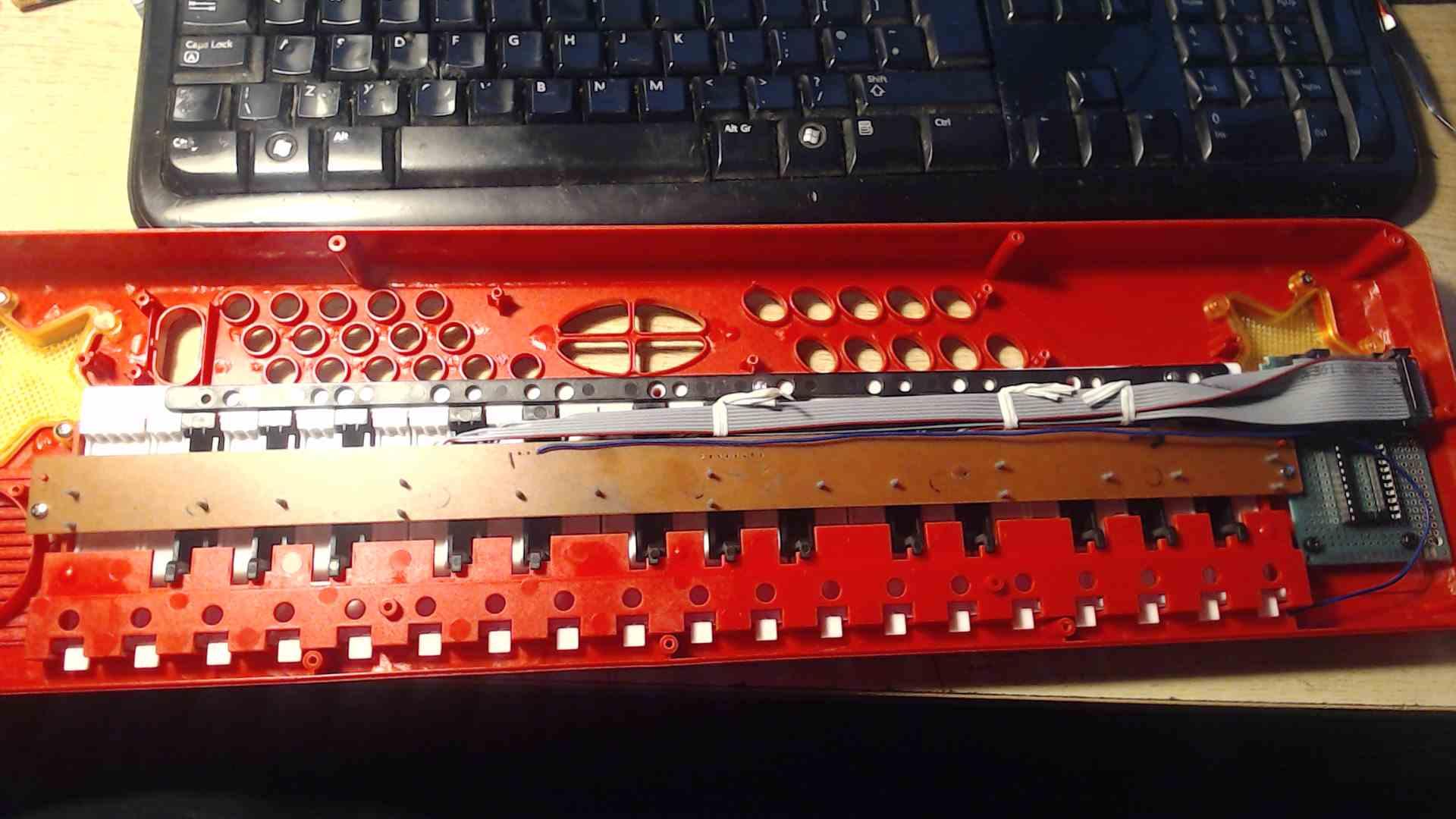
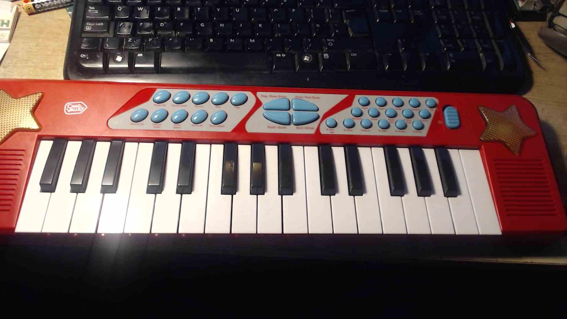
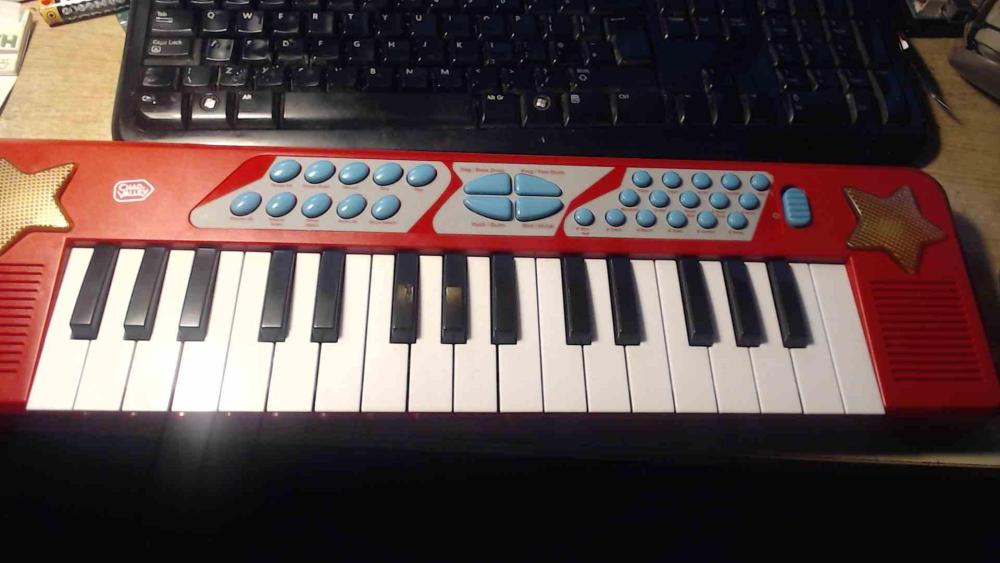
Funnily enough I'm actually right now working on converting a children's toy keyboard into a MIDI controller
-
modification Casio Mt65... adding MIDI control?
IanB replied to the_duckchild's topic in Classic Casio Discussion
@littleghost If you post pictures of both sides of the VL1 PCB we can probably work it out. It's monophonic so it probably doesn't have diode steering to handle key rollover. -
Just skipping around in the video, it looks like the keyboard VLSI is approximately in the middle at 13:14. Oooh, I see an awful lot of connections between PCBs there!
-
Hi @daveb22, something to do would be to get those keyboard PCBs out, shine an angled light source (shadows help) and use a magnifying glass to look for cracks. If the problem isn't there, the bad news is that the whole keyboard is controlled by one custom VLSI chip so it would mean finding a donor machine to donate a PCB more than likely. If you have a tester (multimeter) check the continuity of those jumpers and ribbons. Solder joints can look fine, but be in fact dry. Looking at the dodgy photocopied manual, it looks like the controller chip "MSM-6200GS" is on the same PCB as two octave s(and a bit) of keys. Is the octave that's working on that PCB?