
Etaoin Shrdlu
-
Posts
12 -
Joined
-
Last visited
Etaoin Shrdlu's Achievements
")


-

repair Resurrecting thrift-store found Casio PT-20
Etaoin Shrdlu replied to Etaoin Shrdlu's topic in Classic Casio Discussion
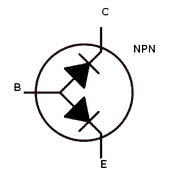
Ideally you would use the diode test mode of your multimeter, if it has this. From the meter's point of view, a transistor looks like two diodes connected from the base to the emitter & collector: To test an NPN transistor: With the meter set to diode test and with the positive lead connected to the base of the transistor you should see a forward voltage of ~0.5-0.8V when touching the negative lead to the emitter or collector. Staying in diode mode, and connecting the negative lead to the base of the transistor you should see no voltage ("OL") when touching the positive lead to the emitter or collector. Switching the meter to resistance mode, with the negative lead still connected to the base, you should see an open ("OL") when touching the positive lead to the emitter or collector. With the positive lead connected to the base you should see zero ohms (or close to it) when touching the negative lead to the emitter or collector. For a PNP transistor everything is reversed: With the meter set to diode test and with the negative lead connected to the base of the transistor you should see a forward voltage of ~0.5-0.8V when touching the positive lead to the emitter or collector. Staying in diode mode, and connecting the positive lead to the base of the transistor you should see no voltage ("OL") when touching the negative lead to the emitter or collector. Switching the meter to resistance mode, with the positive lead still connected to the base, you should see an open ("OL") when touching the negative lead to the emitter or collector. With the negative lead connected to the base you should see zero ohms (or close to it) when touching the positive lead to the emitter or collector. In both cases you should see an open ("OL") when measuring the resistance between the emitter and collector, regardless of the direction you measure in - no current can flow here since our imaginary diodes are pointing in the opposite direction to one another.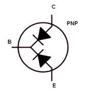
-
repair Resurrecting thrift-store found Casio PT-20
Etaoin Shrdlu replied to Etaoin Shrdlu's topic in Classic Casio Discussion
Oh, and just one more thing... Hopefully this will prevent the same thing from happening again -
repair Resurrecting thrift-store found Casio PT-20
Etaoin Shrdlu replied to Etaoin Shrdlu's topic in Classic Casio Discussion
Mission accomplished! (apart from the lowest note on the keyboard; I'll repair that sometime later, when I've got some graphite paint) Thanks to everyone for their help! -
repair Resurrecting thrift-store found Casio PT-20
Etaoin Shrdlu replied to Etaoin Shrdlu's topic in Classic Casio Discussion
My go-to would be Kynar for PCB trace repairs, but I'm away from home and did not bring any with me. I also miss my inspection microscope, and soldering station (I have to do this repair with a Portasol instead) 😒 I agree plain single strand copper is the only way to go if you need to repair tracks under the rubber contact pads (or possibly conductive paint), but I've routed my wires outside these. I'll try repairing the four graphite bridges in a bit, and there I will use uninsulated copper wire, since it won't touch any other conductive areas. Also remains to be seen whether the white wires going around the back of the board will interfere with the keyboard keys - I may have to reroute these... -
repair Resurrecting thrift-store found Casio PT-20
Etaoin Shrdlu replied to Etaoin Shrdlu's topic in Classic Casio Discussion
After sanding and degreasing the area I superglued a piece of FR-4 on top of the crack, which should make that part of the PCB much stronger than the rest: But the damage was worse than I first thought... 😖 After removing the tape and cleaning up the adhesive residue it became clear that the crack had continued further and had broken another three copper traces, and the four graphite paint "jumpers" going across them: I've fixed all the broken copper traces with solder bridges and bodge wires (I had no Kynar to hand, so had to make do with some thin regular wires), and now the top five chord buttons, and the leftmost one of the middle row, work as they should, but the rest remain silent. I have confirmed that these are all connected to the broken graphite paint bridges. I guess I need to get some conductive paint before I can get any further, unless anyone has a better idea? -
repair Resurrecting thrift-store found Casio PT-20
Etaoin Shrdlu replied to Etaoin Shrdlu's topic in Classic Casio Discussion
Thank you for this amazingly detailed information - you are a wizard! 🧙♂️ I do not have a service manual for the PT-30, or the PT-20, only the PT-80. -
repair Resurrecting thrift-store found Casio PT-20
Etaoin Shrdlu replied to Etaoin Shrdlu's topic in Classic Casio Discussion
Good news, and bad news. The good news is I've figured out why the chord section buttons (and the lowest note on the keyboard) don't work at all, and it's not due to an MCU failure, or any other component. As I was (very gently) washing it, I discovered that the keyboard PCB is cracked, just where the chord section sticks out from the rest 😫 I think the broken traces going to the chord section can be fairly easily repaired (after glueing a reinforcement on the back), but the contact pad for the lowest note on the keyboard is also cracked and that will be a lot harder to deal with... Any suggestions? -
repair Resurrecting thrift-store found Casio PT-20
Etaoin Shrdlu replied to Etaoin Shrdlu's topic in Classic Casio Discussion
Fabulous! I read your post with great excitement, but was disappointed when I looked at my own PT-20; I had already replaced that transistor during a previous repair attempt, and it had not fixed my problem. Indeed mine too had failed open (I've kept the original part, so could double check). Then I had a brief moment where I thought I had found another dead transistor, but after desoldering it I realised it was a PNP and I had simply measured it the wrong way around I decided to spend some time looking at the signals from the CPU - here for example are the Melody Pitch (pin 80) and Melody Envelope (pin 79) signals: That made me feel better again, since these are obviously correct, and the strange sounding instruments must be caused by something fixable. Based on what others had said about dim LEDs, and thinking mine too looked dim I took some voltage measurements (again) and this time I realised they were too low (-4.5V measure -3.7V for example), so I went back to the power supply section on the board and tested the caps for shorts, then the diodes, and... what? The diode between the DC barrel jack and the headphone jack measured 0.1V on diode test, in both directions Whoooa. I desoldered it and confirmed: this diode was dead as a dodo and had a resistance of just 200-ish ohms in both directions. And it sits right across the power rails. Now I'm excited again! I grabbed whatever diode I had to hand (1N4148) and replaced it - and what do you know, IT FRIKKIN WORKED! I can't believe it, but melody and percussion now sound exactly as they should! I still have some other issues to fix; most importantly the chords section is totally mute, and some keys don't work on the keyboard (I suspect a good clean-up will fix those), but this is a huge step forward! Big thanks to everyone who's contributed - and a Happy New Year to you all! -
repair Resurrecting thrift-store found Casio PT-20
Etaoin Shrdlu replied to Etaoin Shrdlu's topic in Classic Casio Discussion
Ah yes, I saw your earlier post and thought I'd ask if my MP3 sounded the same as your PT-20. Interesting. I suspect the fault we're having may have been caused by someone using an adapter with the wrong polarity, which has caused some components to fail. Hopefully that does not involve any microcontroller pins! At least the MCU is still running, so that gives me some hope. Still slowly working my way through the schematic (updated above), but it's a real slog 😒 -
Etaoin Shrdlu changed their profile photo
-
repair Resurrecting thrift-store found Casio PT-20
Etaoin Shrdlu replied to Etaoin Shrdlu's topic in Classic Casio Discussion
Although it most likely won't have anything to do with the fault(s) on my PT-20, while working on the schematic I noticed there's very little in the way of documentation on the Hitachi HD 61914 SRAM chip, which seems to have been a custom jobbie made for Casio. It's an 8-kbit / 1kb static RAM in a 44-pin TQFP package, with a 4-bit bus width, so more than half of the pins are not needed. The thing is, sources differ on which pins are used and which are n/c. The only two sources I've found for pin-out information (the TRS-80 PC-4 service manual, and a Polish Casio FX-700P fan) show lots of pins as n/c which definitely are connected on the PT-20 and PT-30: I'm curious to find out what's going on here, does anyone know? This confusion is a little annoying when I'm trying to produce an accurate schematic of the PT-20... -
repair Resurrecting thrift-store found Casio PT-20
Etaoin Shrdlu replied to Etaoin Shrdlu's topic in Classic Casio Discussion
I have started to painstakingly trace out the PCB, by continuity testing the physical board and looking at a photo overlay of the traces on the component side. It's hard going though, because the layout is quite messy. I have used the D1868G pin designations from the PT-80, which is the closest relative I have been able to find a service manual for. Some of these will not match the PT-20, but I have to start somewhere... For example, the "white noise" output on pin #72 is n/c on the PT-20, which must mean it's using a different pin for this. -
Hi all, I registered here in the hope I might find some help in repairing a lovely little Casio PT-20 I picked up for a couple of Euros in a second-hand shop. It's nice and tidy with no cracks or scratches, and all buttons & keys are present. Sadly there appears to be something wrong with the envelope signal on the melody, and the chord/bass doesn't make any sound at all. Here's a short MP3 which demonstrates what it sounds like, using the rock & bossa nova beats, and piano and organ melody sounds. Clearly a very sick puppy 😟 Some crappy phone photos: The plastic is not nearly as yellow as the photos suggest! I would love to try and fix this lovely little keyboard, but haven't been able to locate a schematic other than for it's much bigger brother the PT-80. This does use the same CPU though, so there's probably a fair bit they have in common. I guess finding the envelope transistor for the melody might be a good place to start; on the PT-80 this hangs off pin #79 on the CPU...