CYBERYOGI =CO=Windler
-
Posts
333 -
Joined
-
Last visited
Content Type
Profiles
Forums
Downloads
Everything posted by CYBERYOGI =CO=Windler
-
 Did it ever got wet by conductive (salty, sour, battery-) liquids? If the stuff is still on the PCB, it will later react more sensitive to moist air and corrode much easier if not removed.
 -
PT-31 - won't power on.. Where to start?
CYBERYOGI =CO=Windler replied to 534N's topic in Classic Casio Discussion
MT-52 has different firmware in its NEC D930G CPU than MT-65/68, thus they likely can not be upgraded. (I haven't analyzed the keymatrix by myself yet.) software number hardware class notes & features 011 MT-65, CT-7000, RC-1 original version with 3x4 accompaniment variations 013 CT-620 61 keys support (changed matrix layout), arpeggio & bass volume pins swapped 017 MT-800 (old) ROM-Pack support, different preset sounds & rhythms 018 MT-85, MT-800 (new) same like 017? (bugfix release?) 019 MT-210 uses percussion IC M6202-19, some preset sounds changed 020 MT-52 Super Drums support, different preset sounds & rhythms 022 MT-500 Super Drums support, uses percussion IC D934G, different preset sounds & rhythms The Casio KX-101 is no relative of MT-65 either but rather a 4-note polyphonic sort-of PT-30 with very different software. CPU1= "NEC D1868G 006" (80 pin SMD) CPU2= "NEC D1879G 002" (80 pin SMD) The D1868G with different firmware was else used in PT-30-like keyboards. software number hardware class notes & features 001 PT-30 LCD support + datasette module, uses SRAM HD61914B 004 PT-50 LCD & ROM-Pack support + datasette module, uses 2x SRAM HD61914B 006 KX-101 combined with "NEC D1879G 002", uses 2x SRAM HD61914C, datasette storage 007 PT-80 ROM-Pack & key leds support A01 (HD61703) MT-18 same like 007 B01 (HD61703) PT-82 ROM-Pack & key leds support, no chord buttons -
When the keyboard is ice cold (e.g. left in a car in winter) and bought into a warm moist room, water can condense inside and short contacts of the keyboard matrix, which results in sensing wrong key and button presses. I guess the situation needs to be a bit extreme to make it fail, but I own e.g. a Micronta - Vox Clock 2 talking alarm clock, which reset input of the sound CPU is so high resistance, that it crashes during high humidity (or when huffing moist air on the capacitor) and so only plays a pop/click noise instead of talking when the atmosphere is way too moist.
-
The term "DSP" is relative. Some may use it as a generic term for postprocessing effects within softsynths. Even very poor sounding Bontempi 1980th toy grade lofi keyboards were advertised to have a "digital signal processor". By the way, I found the likely world first single-chip softsynth. It is the "Sound FX Phasor" by the unknown British company Electroplay made in 1980 (1 year before Casio VL-1!) - a soundtoy in the shape of a handheld barcode scanner computer, which foil touchpad has only 16 buttons (15 act as "white" keys, no sharps), and the synthesizer is running on a tiny PIC microcontroller with only 768 byte ROM + 32 byte RAM. Beside 8 preset effect noises it has a keyboard mode with synthesizer, featuring suboscillators with multipulse squarewave and freakish siren-like howling modulations. The monophonic sounds are even more complex than VL-1. Particularly it can do sonorous organ-like bass notes and crunchy motor noises with simple decay envelope and also strange semi-metallic gongs and clangs. The grainy lo-fi sound engine employs program loop synthesis in the style of Williams early electronic pinball machines. But unlike VL-1 it is more centered on less melodic howling effects, and often resembles random glitch stuff with strange techno sound loops those can include crackle, buzz and rough pulsing or bleeping noises, so it can be somewhat compared with POKEY (the famous Atari 8-bit soundchip). But the relation is more like that of Phase Distortion to FM - despite similar principles, the character of the timbres and its parameters can substantially differ and make of it a unique sound source. The Sound FX Phasor was way ahead of its time. This is the same type of British low-cost miracle like the first Sinclair homecomputers. It could have been a game changer; under different circumstances UK instead of Japan would have created the VL-Tone. But the user interface is awful. There is no sequencer, synth patches can not be saved and most obnoxious is that auto-power-off deletes the created patch (up to 31 key presses) after 46 seconds of idle. The single page manual does even try to explain the synth parameters (6 letter buttons, each 0..255?), and the software seems full of bugs those cause semi-random behaviour. Fortunately I managed to dump the rom code and make schematics to reverse-engineer this amazing technical marvel. Likely it can be emulated, and perhaps I will write a better softsynth of the algorithm to turn it into a well playable instrument.
-
Possibly conductive liquid (battery acid, cola, salt water etc.) has flown inside and randomly shorts contacts. You may need to wash the PCB with water and dishwashing soap (rinse well, towel dry and possibly dry with hairdryer at low heat) to remove residues. Important is, do not connect to electricity/insert battery so long it is wet (else it corrodes) and keep the speakers dry (desolder them) because the diaphragm is likely paper that gets ruined by water. But it may even be that your keyboard is not broken at all but reacts on strong electromagnetic fields e.g. by a nearby radio transmitter. Unlike the human brain, modern keyboards unlikely get messed up by mobile phone radiation, but if the keyboard is older than about year 2000 or there is something else (e.g. a high power HAM radio) transmitting nearby, it can freak out by that. E.g. the computer keyboard of my Amiga (built into a wooden custom cabinet) started to type random characters when teenagers in a room above mine used a CB radio. Moving the keyboard cable reduced sensitivity to it.
-
PT-31 - won't power on.. Where to start?
CYBERYOGI =CO=Windler replied to 534N's topic in Classic Casio Discussion
On my PT-30 the reset ("P") button is vital for operation! By a hardware bug, the PT-30 tends to crash (lockup) during battery insertion and will not respond to controls anymore. If this happens, switch it on and press the tiny "P" (reset) button at the case bottom with a pointed object to clear memory (erases sequencer contents). To avoid the crash, if the instrument was left without batteries for over a minute (which corrupts SRAM contents) always slide the mode switch into "play" position before inserting batteries or connecting a power supply. However your model is a different version that may use a capacitor for automatic reset (thats how it should be made) when inserting batteries. Interesting is that your PT-31 has a different PCB layout with smaller analogue PCB. It looks like severely damaged by battery acid vapours, so chances are high that also the through-hole contacts on the PCB corroded away. If any copper traces have black spots under the green coating, they likely won't conduct anymore and need a wire soldered across to fix them. I patched together a severely battery damaged PT-50, which was a nightmare to repair because e.g. the chord button panel traces were completely corroded away. To a novice this is hopeless. See here what may await you: When exposed to battery acid, there is also a high risk that the LCD or its foil cable has decomposed. (Do not scribe the foil with pencils etc. - any friction, folding or pulling will make it flake apart even worse! There is no simple fix, except installing a foam rubber strip (window insulation adhesive tape) to press the ends against the PCB and display glass if they came loose.) But first replace the 2.2k tuning trimmer, else the CPU may get no clock frequency and can not run. That it came loose looks like result of battery acid. The tape interface cartridge TA-1 was AFAIK an expensive optional luxury addon that is extremely rare now and surely never came pre-installed in any Casio keyboards. Casio MT-65 chips have nothing common with PT-30/PT-31 and definitely can not be replaced with them.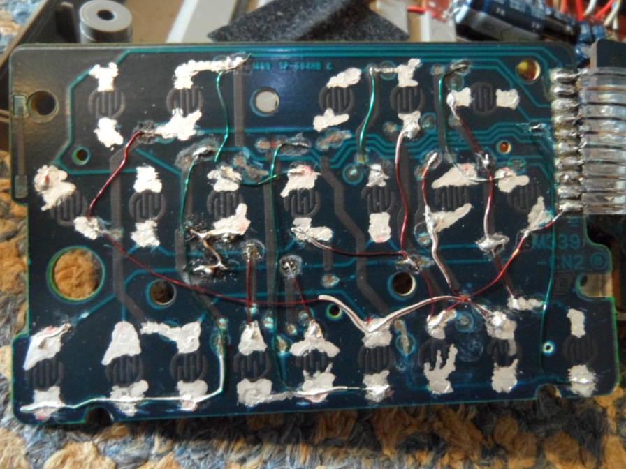
-
Does the CT-S1000V app work within an Android emulator for PC (Windoze or Linux)? It is a major atrocity of planned obsolescence to design a keyboard that depends on a brainfryer that makes it become e-waste by turning incompatible 2 smartphone generations later or once the app gets removed from the appstore or cloud by lack of commercial interest. It needs to be made a legal requirement against e-waste to make musical instruments etc. compatible with real PCs instead of locked cloud-only throwaway gadgets those cause brain damage by pulsed microwaves.
-
MT-400v - Having some problems. Any ideas?
CYBERYOGI =CO=Windler replied to 534N's topic in Classic Casio Discussion
For lubrication of plastic parts I only use silicone based grease/oils. Any other fat/oil may decompose plastic over time (may take weeks or >10 years, but not suited for long term preservation). Thin silicone oil is good for fast spinning or very low friction parts (fan bearings, seconds-hand cog in quartz clock movements), but because it moves around/may evaporate, I use for slow moving parts a tube of "NASP SILIKONPASTE N.D.P. (no dropping point) - SILIKONFETT - SILIKON + P.T.F.E." (somewhat expansive but lasts long, found on eBay), which is a white grease that also contains teflon nanoparticles to distribute point loading (hence do not use it for water taps - that's nanoplastics). But there are warnings that silicone oil may damage silicone rubber (non-silicone oil dissolves e.g. latex rubber), so better keep the lube away from silicone rubber key/button contacts (not all are actual silicone, which complicates the situation). Otherwise some rubber contacts (e.g. under scratch disc in toy DJ consoles) are designed to be lubed and may quickly wear out when dry, so this is a "wash me, but do not make me wet" situation without a single correct solution. Also keep any lubes/oils away from Casio's infamous metalfree LCD foil cables. If in doubt (and nothing squeaks, gets stuck etc.) do not lube at all. Do not fall for claims like "conductive" lubricant. Actual electrically conductive lube (e.g. graphite powder) would cause shortcircuits everywhere it spills and is only useful for very special cases (high current motors etc. - definitely not analogue audio). Normal electric contact lube is designed such that metal/carbon contacts can still pinch through the grease film enough to conduct electricity, but it is not conductive by itself. The Yamaha white grease is likely a similar silicone based substance like "NASP SILIKONPASTE N.D.P." -
MT-400v - Having some problems. Any ideas?
CYBERYOGI =CO=Windler replied to 534N's topic in Classic Casio Discussion
The problem is that a potentiometer track is not a solid block of *pure* carbon. It is a paint containing carbon particles in a binder, which depending on its composition (in worst case something like nitro lacquer or spirit lacquer) may dissolve by organic solvents and so flush the carbon powder away. While I have successfully cleaned some pots with Isopropanol (e.g. a Casio MT-70 which is delicate to dismantle for access), e.g. slide pots in 1980th Bontempi keyboards react extremely sensitive on such chemicals. Thus I recommend to clean only with distilled water and a cotton swab (and dry it well) if you can desolder and open it (many slide pot tracks can be accessed without). Already the DeOxit statement "Mineral oil will not damage metals, plastics and carbon" is debunked, because mineral oil (e.g. household "machine oil") does make Bakelite (which by definition is a "plastic") brittle and crumble apart like charcoal, which is e.g. an infamous problem with spilled machine oil on Hammond organ parts. And the statement "If they use one of our sprays with a solvent, if the carbon has been scratched or damaged, the solvent will flush it off the surface." means that it does remove unbonded carbon particles (like a pencil streak), but poorly made old pot tracks are more like a pencil streak than a solid coal block. Therefore there is also the warning not to clean potentiometers in ultrasonic cleaners. Modern pots may be chemically and mechanically robust (like carbon brushes for strong motors) and even certified with a guarantee to survive PCB cleaning solvents used in factories. But ancient potentiometers are a different cup of pee. If the track is of nitro or spirit laquer, then Rest In Pieces. By the way, I have successfully repaired broken carbon tracks with conductive carbon paint based on such lacquers, those of course are not resistant to solvents either. Also a soft pencil can be used to patch a damaged carbon track, which isn't particularly stable either. And the reason that in the test with DeOxit the knob rotates much easier is because the shaft bearing/sleeve intentionally contains a viscous grease (may be to stop dust and make it feel more solid) that likely got washed away. That grease tends to solidify/form resin over time which makes the knob hard to turn. -
New casio SA keyboards
CYBERYOGI =CO=Windler replied to XW-Addict's topic in General Casio Discussion
They need to make a version of the classic SA-series sound engine with USB midi and fully editable synth parameters (on device/midi parameters - NOT obnoxious brainfryer app crap). Also a velocity sensitive variant resembling Yamaha PSS-A50 would be interesting. -
CZ-101 Troubleshooting at various stages!
CYBERYOGI =CO=Windler replied to momo's topic in CZ Series
Check if the clock oscillator (needs oscilloscope) and reset capacitor are ok. In my AVR Transistor Tester the crystal died and so made it not start and make random problems. After soldering a new quartz in, the thing works perfectly. If reset is stuck (shorted cap) it will pretend totally braindead. Also an interrupted (high resistance) cap may make it not wake up properly. I have a Sharp talking alarm clock which reset input is such sensitive that when the cap develops only minor internal short of some 10 megohms (even temporary by air humidity), the display stays blank and nothing works. I replaced that same capacitor already 3 times and other in related hardware. Even rosin flux residues from soldering can conduct enough to make the thing fail, and of course battery leak residues (even vapours) also may make the epoxy conductive enough. Adding a pullup/pulldown resisitor of 1 megohm or such would likely permanently fix that, but also eat a bit more standby current and so drain batteries. -
MT-400v - Having some problems. Any ideas?
CYBERYOGI =CO=Windler replied to 534N's topic in Classic Casio Discussion
The special hardware in MT-400V/CT410-V is only the analogue VCF with sliders. Do NOT attempt to use contact cleaner in those slide potentiometers. It may dissolve the carbon track (has nothing to do with "dry out" or whatever) and permanently destroy them! Contact cleaner is for metal contacts only, so also do not clean carbon contacts on the PCB with it. Before trying anything harsher, first try to only suck dust out by vacuum cleaner (on low setting) and play a round of Decathlon (move 20x quickly to both ends) on the sliders. If it doesn't help, you may insert a cotton swab with isopropanol or (safer) destilled water to clean the track, but do not press hard, else it may ruin it. (Let it dry before use.) If the track is broken/worn anyway, you may try to fix the gap with soft pencil (the graphite conducts electricity). -
CTK 1000 Power Input
CYBERYOGI =CO=Windler replied to GreyHawk4749's topic in Classic Casio Discussion
Casio had always PSU plugs with negative center polarity. Never try to use one (e.g. from Yamaha) with positive center, else it may fry the entire electronics. Only in very new keyboards (like SA-46) AFAIK also Casio changed their polarity to positive. -
Very Rare Casio Organ: Symphonytron 8000
CYBERYOGI =CO=Windler replied to Display Name's topic in Classic Casio Discussion
Yes, I still have the CT-8000, the RC-1 and a defective MB-1. I do not own the pedal board, speakers and 2nd CT-8000 (nor enough space to install a complete system). If anybody has hardware photos or eprom dump of the pedal board FK-1, please upload it. Here are a few words I wrote about it. Casio Symphonytron 8000 A successor of the Casiotone 202 was the similar Casio CT-8000 keyboard (additional stereo chorus, reverb, only 1 vibrato, no speaker), which was part of the ultra- rare modular stage organ Casio Symphonytron 8000. (I read that only 100 specimen were made. I downloaded the manual.) This expandable organ system from 1984 was assembled from the following detachable units: 2x keyboard CT-8000 dual keyboard stand CS-200 (with integrated audio mixer) auto accompaniment unit RC-1 memory unit MB-1 (sequencer, uses RAM-Pack RA-2) pedal keyboard unit FK-1 foot volume pedal VP-2 2x sustain pedal SP-1 2x speaker combo amp AS-10 (small) or AS-120 (medium) or AS-1000 (large, with reverb) A smaller expansion level used only one CT-8000 on the stand CS-100. The CT-8000 could be also used separately with an external amp; there was even a hard carry case HC-11 made for it. some main features: per keyboard 49 fullsize keys polyphony 8 notes per keyboard monophonic pedal bass voice 49 preset sounds {piano 1..4, honky tonk piano, zimbalon, synth. sound, harpsichord 1..2, celesta 1..2, marimba, harp 1..3, koto 1..2, taisho koto, banjo, mandolin, guitar 1..3, elec. guitar 1..5, elec. bass, pipe organ 1..5, accordion, bagpipe, oboe, clarinet, flute, shakuhachi, wawa, horn, flugel horn, trumpet, brass ensemble, string ensemble, violin, cello, double bass} selected by keyboard keys + mode switch 18 pedal keyboard preset sounds {organ 1..4, tuba 1..2, bassoon 1..2, wood bass (arco) 1..2, wood bass (pizz.) 1..2, elec. bass 1..2, harpsichord 1..2, piano, synth. chime} selected by pedal keys + mode switch 16 semi- OBS preset rhythms {rock, disco, 16 beat, samba, beguine, swing 2 beat, waltz, slow rock | rock 'n' roll, march, cha-cha-cha, bossa-nova, lating swing, swing 4 beat, jazz waltz, shuffle} versatile accompaniment with each 2 arpeggio & bass variants semi-analogue percussion keyboards with sustain, reverb, vibrato, stereo chorus The silver metallic painted system was heavy and quite a mess of plugged cables since it lacked a clever multicore or bus concept. Furthermore it was infamous for its flimsy combo amp speakers, those thin pressboard cabinets crumbled apart by rough handling or humidity, which made it not really stage-proof. Not least because it came out during the end of the home organ hype, it was a commercial flop, and so only few demonstration specimen were built. The Symphonytron had 49 preset sounds (in each keyboard) and the monophonic bass pedal keyboard had 18 keys and preset sounds. The accompaniment unit had 16 preset rhythms. The lower keyboard was also used for accompaniment. The voice of the lower keyboard could be layered with the upper keyboard, and both keyboards also could be detuned and transposed against each other for additional sound variation. With 2 keyboards present, there was an additional harmonizing mode (likely layering both keyboard voices in a special way). You can also combine rhythm with manual chord etc.; the accompaniment was similarly versatile like with Antonelli 2495. The editable polyphonic realtime sequencer recorded all sounds (947 steps in total, 58.5 steps of these only for function select events, all of them shared among up to 4 songs) and could save them to the RAM-Pack RA-2. (Note: Despite the "8" in its name, the Symphonytron 8000 and its CT-8000 keyboard unit had neither a ROM-Pack slot nor key lighting.) I got on eBay only one CT-8000, the RC-1 and a defective MB-1 in very beaten up condition (full of scratches, dirt and glue residues). Because it lacked the special DIN14 cables, I ordered 3 Atari ST floppy cables, those work perfectly with the RC-1 (with one keyboard it does key split accompaniment with arpeggio, and also the trio mode works). Like with Kawai MS20, when you set a preset sound on the keyboard it plays a short fanfare with it (always the same notes). How ever my MB-1 doesn't work at all (buttons don't respond and it makes sometimes a louder growing digital buzz); possibly the eprom is dead. Also CT-8000 and RC-1 contain (as the only Casio instruments I know) each a soldered eprom; I backed up all 3 to avoid data loss. The multi-chip hardware is quite complex and particularly the RC-1 and MB-1 have several stacked PCBs in their crowded case. Fortunately there are are some pinout marks on them, those may help to decipher them. The MB-1 and CT-8000 both have the same CPU "NEC D8049C 364" (Intel MCS-48, I dumped its firmware) with sound IC "D931C 011". The RC-1 CPU is a "NEC D930G 011". So they are far relatives of the Casio CT-410V hardware class (minus the VCA, but with external ROM) which may help to research hidden functions of its chip set. I don't own the FK-1 pedal board, so I have no clue what is inside. -
I used a piece of sturdy insulated copper wire to replace that broken hook if missing, and hotglued it under the key. If the plastic hook can be found inside the case, it can be superglued back into place. I recommend to remove the keys assembly for this or at least leave the case open for 8 hours, because superglue vapours may permanently discolour transparent parts of the LCD white if they can not escape.
-
I have no service manual of the PT-100. Some discrete percussion filter parts likely differ from other models, but the rest can be concluded without. Here is some more CPU info, if anybody needs it. pinout HD61702 caution: The service manuals indicate that this CPU uses "negative logic", i.e. technically +5V is its GND while 0V is its -5V supply voltage. So the voltages are not was the pin names suggest. I use the positive voltage naming convention (from 0V to +5V, not -5V to 0V). pin name purpose 1 FC6 melody filter switch out (fine) | in MT-520: chord filter switch 2 FC7 melody /mute switch out 3 MNOISE metallic noise out (for analogue percussion) 4 WNOISE white noise out (for analogue percussion) 5 VDD1 ground 0V 6 VDD2 rom pack pin 4 | in MT-520: percussion ic ground 7 GC (+2.3V in MT-88) 8 GND0 supply voltage +5V 9 GND2A DAC O2A supply voltage +5V 10 O2A chord audio out (upper bits) | in MT-520: melody beta audio 11 O2B chord audio out (lower bits) | in MT-520: melody beta audio 12 GND12B DAC O1B, O2B supply voltage +5V 13 O1B melody audio out (lower bits) | in MT-520: melody alpha audio 14 O1A melody audio out (upper bits) | in MT-520: melody alpha audio 15 GND1A DAC O1A supply voltage +5V 16 GND4A DAC O4A supply voltage +5V 17 O4A obligato+base+hi conga+lo conga audio out (upper bits) | in MT-520: bass audio 18 O4B obligato+base+hi conga+lo conga audio out (lower bits) | in MT-520: bass audio 19 GND34B DAC O3B, O4B supply voltage +5V 20 O3B bass+cymbal+hihat+snare audio out (lower bits) | in MT-520: chord audio 21 O3A bass+cymbal+hihat+snare audio out (upper bits) | in MT-520: chord audio 22 GND3A DAC O3A supply voltage +5V 23 VDAC1 DAC ground 0V 24 VDAC2 DAC ground 0V 25 /O11 (stays hi, not used) 26 O11 (stays lo, not used) 27 O12 melody DAC /LSB (not used) 28 O13 melody DAC LSB (not used) 29 O14 melody DAC LSB (not used) 30 O15 melody DAC LSB (not used) 31 O16 melody DAC2 LSB (not used) 32 O21 chord DAC /LSB (not used) 33 O31 bass+cymbal+hihat+snare DAC /LSB (when blip percussion, else hi | not used) 34 O41 obligato+base+hi conga+lo conga DAC /LSB (not used) 35 GND5 supply voltage +5V 36 GND2 supply voltage +5V 37 GND1 supply voltage +5V 38 OSI clock in (7.808MHz) 39 OSO clock out 40 KI1 key matrix in | MT-520: snare pad 41 KI2 key matrix in | MT-520: base pad 42 KI3 key matrix in | MT-520: clap pad 43 KI4 key matrix in | MT-520: rimshot pad 44 KI5 key matrix in | MT-520: lo bongo pad 45 KI6 key matrix in | MT-520: hi bongo pad 46 KI7 key matrix in | MT-520: cymbal pad 47 KI8 key matrix in | MT-520: hihat pad 48 MI power switch on 49 RESET reset 50 DTE (wired to ground) pin name purpose 51 TEST (wired to ground) 52 /WE ram write enable 53 /CE1 chip enable (ram, rom, percussion ic) 54 CE2 rom pack pin 2 55 C1 rom pack pin 5 56 C2 rom pack pin 6 57 OP rom pack pin 7 58 D0 data bus (ram, rom, percussion ic) 59 D1 data bus (ram, rom, percussion ic) 60 D2 data bus (ram, rom, percussion ic) 61 D3 data bus (ram, rom, percussion ic) 62 D4 data bus (ram, rom, percussion ic) | rom pack pin 8 63 D5 data bus (ram, rom, percussion ic) | rom pack pin 9 64 D6 data bus (ram, rom, percussion ic) | rom pack pin 10 65 D7 data bus (ram, rom, percussion ic) | rom pack pin 11 66 LO1 key led out | in MT-520: key matrix out, address bus A12 out 67 LO2 key led out | in MT-520: key matrix out 68 LO3 key led out 69 LO4 key led out 70 LO5 key led out | in MT-520: rom /CS 71 LO6 key led out | in MT-520: ram /CS 72 LO7 key led mux out | in MT-520: percussion ic /CS 73 LO8 key led out | in MT-520: tempo led out 74 LO9 key led out | in MT-520: record led out 75 LO10 key led out | in MT-520: rhythmSel2 /rhythmSel1 led out 76 LO11 key led out | in MT-520: toneSel2 /toneSel1 led out 77 LO12 key led out | in MT-520: drumpad flipflops read out 78 LO13 key led out | in MT-520: drumpad flipflops clear out 79 LO14 key led mux out | in MT-520: /APO auto-power-off out 80 VDD3 ground 0V 81 GND3 supply voltage +5V 82 CKM2 clock/2 out 83 KO1 key matrix out, address bus A0 out, base trigger 84 KO2 key matrix out, address bus A1 out, snare trigger 85 KO3 key matrix out, address bus A2 out, claves trigger 86 KO4 key matrix out, address bus A3 out, lo conga trigger 87 KO5 key matrix out, address bus A4 out, hi conga trigger 88 KO6 key matrix out, address bus A5 out, hihat trigger 89 KO7 key matrix out, address bus A6 out, cymbal trigger 90 KO8 key matrix out, address bus A7 out 91 KO9 key matrix out, address bus A8 out 92 KO10 key matrix out, address bus A9 out 93 KO11 key matrix out, address bus A10 out 94 KO12 key matrix out, address bus A11 out 95 VCON (stays hi) 96 FC1 tempo led out | in MT-520: melody gain & filter switch out 97 FC2 memory led out | in MT-520: melody gain & filter switch out 98 FC3 percussion trigger mux out | in MT-520: melody gain switch out 99 FC4 /APO auto-power-off out | in MT-520: melody gain switch out 100 FC5 melody filter switch out (coarse) | in MT-520: bass filter switch out The analogue percussion trigger signals (used in MT-88) are multiplexed with the key matrix outputs KO1..KO7; they can be decoded by AND comparison with pin 98 FC3. Depending on 2 fixed key matrix diodes, the CPU output either analogue percussion triggers or blip percussion, but not both, so there is no easy way to mix them. The 'claves' is used only as a signal (memory button click, ROM-Pack error) but not in rhythm. In blip percussion mode FC3 outputs only a shorter tempo led pulse. The hiss waveform outputs 3 MNOISE and 4 WNOISE seem to be shift register feedback noise; they apparently need to be initialized, because they only start working after first use of rhythm. Pin 33 O31 works only with enabled blip percussion; with analogue percussion it stays hi. Because the MT-520 hardware has a percussion IC and so doesn't need the CPU percussion channel, it uses the surplus polyphony to layer 2 audio outputs (named "melody alpha", "melody beta") for a thicker main voice in the manner of classic Consonant-Vowel synthesis, and it does a stereo chorus in software; for this it delays the alpha or beta melody channel by FM and externally mixes them with opposite phase into stereo channels. Because drumpad hits can be faster than the keyboard matrix scan cycle, for buffering the 8 drumpad inputs each set a flipflop. To read their contents, the CPU sets LO12 high, which makes the flipflop bank appear on the KI lines of the keyboard matrix. Afterwards it sets LO13 high to clear the flipflops to get ready for sensing new drumpad hits.
-
Well, except violins (stradivarius often got puzzled back together from a zillion of tiny wood debris) also acoustic instruments can not last forever. Mouth blown woodwinds rot by moisture, and also many pianos and particularly pedal harps become an economical total-loss after some decades due to worn mechanism. But at least in theory any component of them can be fully understood and remade by craftsmen.
-
I have reuploaded the manuals here: https://www.casiomusicforums.com/index.php?/topic/4797-very-rare-casio-organ-symphonytron-8000/
-
Features I miss on newer Casio keyboards
CYBERYOGI =CO=Windler replied to Pravito's topic in General Casio Discussion
We need a "pro mode" with simple synth to edit internal parameters. At least something like the Casio VL-1 "ADSR" mode (simply type any 8 digit number to create a sound) should be part of even the cheapest toy grade keyboards. The accompaniment section should definitely accept non-chord key combinations to play disharmonic note cluster staccatos. The many synchro start and chord memory combinations of early 1980th keyboards were much more interesting (use plain rhythm with manual chord, stop rhythm during chord section key release to stutter rhythms etc.). I also miss sustain and vibrato on/off button and the good old optional arpeggio control in modern home keyboards. -
using the wrong power supply with CZ101
CYBERYOGI =CO=Windler replied to iamdamosuzuki's topic in CZ Series
I do mostly use unregulated 1A wallwart PSUs with my Casios, those will always show a higher voltage than rated (e.g. 18V in 12V mode) when not burdened by the rated load (that would be 1A). Thus I set the voltage lower (e.g. 6V instead of 9V); too low voltage will distort sound (and may crash) and nor properly light the power LED of the instrument. Really destructive is only wrong polarity. Casio keyboards (like most others) have voltage regulators those filter moderate overvoltage, but may overheat or short when way too high. Only cheap noname toy keyboards (Yongmei and such) may connect its single chip CPU directly to the battery compartment and PSU jack, so it may get fried by as little as 0.5V overvoltage if only the die itself contains a zener diode to pull down surge voltage spikes but will overheat and burn up the chip by few seconds of too high supply voltage. -
You can buy on eBay conductive carbon paint. It is normally intended for repairing PCB traces or EMF shielding, but it may also work to fix the black carbon rubber contacts of the keyboard silicone strips. In cheap keyboards where individual contacts of the strip were destroyed/torn, I occasionally cutted out that dome and replaced it with a piece from another keyboard or cheap calculator with similar domes (independent of the contact strip layout). It might also work to glue only the carbon rubber dot of something else on the strip using silicone bathroom sealant or fishtank glue (be very careful not to soil the conductive side). However it may be that for velocity sensitive keys it will feel to uneven.
-
Retrobrighting Vintage Casio's Keys? (SA-21)
CYBERYOGI =CO=Windler replied to timbr's topic in Classic Casio Discussion
AFAIK Casio's aren't overly light sensitive, but by design the keys may be rather ivory colour than plain white to mimic the key colour of traditional pianos. One reason for the rumbling batteries and yellow keys inside your SA-21 may be leaked batteries, those acid vapours decompose the foam rubber strips (also damage LCDs) and can yellow the plastic. A hint for this would be when the inside (which gets barely exposed to sunlight) is as yellowed or even beiger than the outside of the keys. However my TrendLine MC3700 (bought used, likely a Medeli product) does have extreme sunburn from the previous owner, i.e the white keys are discoloured deeply orange and the coloured buttons brownish (no, it's not nicotine). I haven't dared to use bleach yet because I feared things to crumble apart. The old eBay photo on my website does not show the actual condition of the thing. http://weltenschule.de/TableHooters/Fujiyama_KS-37.html I also own a big green DJ toy keyboard "Synth Mixer" (likely made by Potex, bought used on eBay) which has some of the keys noticeable yellowed. Also the homecomputers and game consoles (Atari 800XL, NES etc.) I had on the desk in 1990th became definitely beige instead of grey. And also the beige of my main PC (Highscreen Colani bigtower, very modded with 2 mainboards inside) and its Chicony keyboard turned beiger by sun over time. But I can not use bleach there because the case has printed logos and is painted inside with EMF shielding paint, and I have additionally hotglued dozens of LEDs and connectors with thin wires into the back of the case front.- 4 replies
-
- 2
-

-
- restoration
- sa series
- (and 1 more)
-
The stairwave engines (Consonant-Vowel and variants) sound cleaner than samples because it uses a very high internal mixing frequency (500 kHz or such) that prevents glassy sounding DAC aliasing noise. In opposite, the sample based/PCM engine softsynth DAC output frequency is much lower (like a CD, afaik with older Casios even less) and so overtones of similar frequency can intermodulate with it and cause aliasing noise. This also affects modern "synthetic" sounds of the softsynth, those are technically not samples.
-
Your First Casio Keyboard Was / Is ?
CYBERYOGI =CO=Windler replied to Scottym's topic in General Casio Discussion
My first Casio was likely MG-880 (a melody calculator with game) followed by either ML-90 (another melody calculator) or finally the Casio VL-1. I placed that on grandma's living room radio, set to AM (between 2 stations) to produce all kinds of strange distorted synth noises. -
Rip off or licenced Casio SA-46?
CYBERYOGI =CO=Windler replied to Chas's topic in General Casio Discussion
When a bootleg plastic case of a device has same size but some details changed, it may even be that the manufacturer copied the mould by scanning the case of an original from inside and outside to replicate it, because development of injection moulds is complex (needs to compute material thicknesses to prevent cracking or distortion during cooldown etc.) and severely expensive. When the design is taken from an older out-of-production device, it can also happens that the original mould was bought/found as scrap and put back into use.